Exhaust Fan Installation
Our basement bathroom did not have an exhaust fan. Since the ceiling was drywall and the basement completely finished, this made installation more of a challenge. The primary decisions I had to make were where in the bathroom ceiling to install the fan and where to exhaust it outside. Part of the ceiling in the bathroom had a soffit drop above the toilet area and was close to the outside wall. After some investigation I decided to install the fan in the soffit drop as it would give me more room to work.
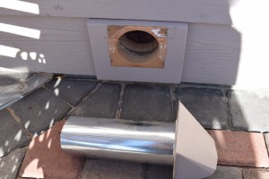
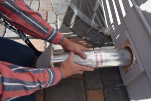
The year before I had installed the exterior vent when we were adding pavers in the backyard. I needed to raise the siding up where the pavers went so I drilled the hole and installed the block then while the siding was off. That way I could seal everything correctly. I installed the vent cover and taped the flap down until I was ready to install the fan.
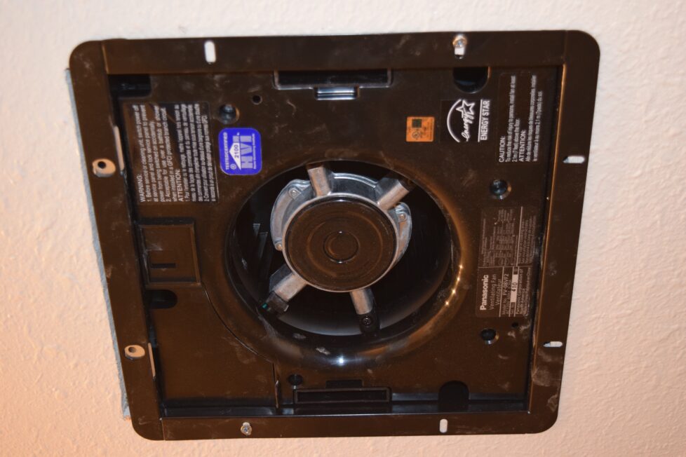
After researching Panasonic fans, I ordered the WhisperFit FV-08VF2. I wanted it as quiet as possible and yet big enough to exhaust properly. After some calculation, the 80 cfm and sone rating (noise) was sufficient for the room size and noise level I wanted.
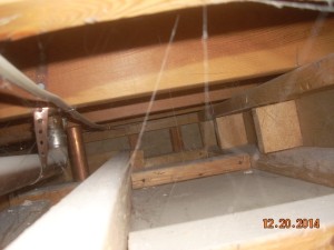
My first step to locate the fan was to use a stud finder and determine where the support members were in the soffit in the area where I wanted to install. I have an access hole in an adjacent wall where my sprinkler shutoff is and I was able to stick a digital camera up in the area and shoot towards the area where I wanted to install the fan. After several attempts, I was able to get a good photo that gave me an idea of how the area above the soffit was constructed. The stud finder confirmed the framing.
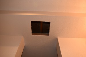
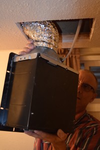
After verification, I marked the area to cut for the opening in the drywall, and cut the hole slightly larger than needed so I could get the fan in. The exhaust port and electrical wiring box on the side of the fan required me to angle the fan up and in to the hole, thus the over sized hole (that will be covered by the vent grill.
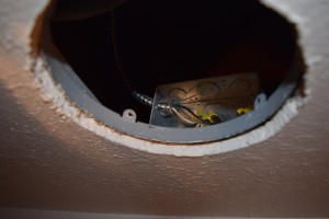
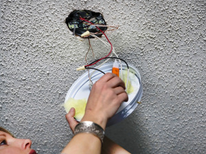
For the power, you need to decide if you want it on a separate switch or connected to a light fixture to come on when the light is on. I wanted it on when the light was on. There was a recessed light that was about 3 feet away. I removed the light cover and then the 3 screws that held the can and pushed the can up into the ceiling. This exposed the electrical connection box of the light where I could run my wires from the light to the new fan. Be sure to run the same gauge of wire as the light is wired with.
Mine was 12/2. Wiring was easy, black to black, white to white, and copper grounds together using three wire nuts. When all connections were made, I pushed the wires back into the box and replaced the wiring cover. I attached the recessed can back to the retaining ring, attached the cover on to the fixture and screwed in the bulb.
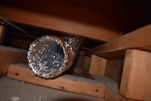
For venting, hard piping is always best, but I knew that I could not configure hard pipe in the concealed area. I was able to add a 38” extension of hard pipe on my vent to get it into the area above the dropped soffit. I put it together, taped all the joints, and attached a piece of 4” flexible aluminum duct to the end of the pipe.
I inserted the vent piping through the hole on the outside and sealed and screwed the vent down. Do not use the flexible vinyl duct.
I attached the new 12/2 wires from the connection box on the recessed fixture to the wires in the connection box on the exhaust fan. After connecting the flexible duct to the fan, I taped and clamped the flexible duct to the fan. The tape I used for all the joints is UL listed duct tape. It is an aluminum faced tape designed for this purpose. Do not use “duck tape” that some associate as the same thing. It is not. You can screw the joints together with short self-tapping sheet metal screws plus the tape if you want.
Once all the connections are made, I tested the fan to be sure the wiring was ok before I inserted it in the hole. I pushed the fan up into the hole and screwed it in with 4 wood screws. Note; screws on one side hit framing already there in the soffit. On the other side, I added a piece of 3/4” wood that I screwed to existing framing. This allowed a solid mount for the fan. I could not use the hangers that came with the fan. If the area had been in an attic, I could have used the hangers.
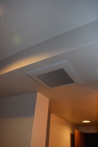
Insert the spring retainers on the cover in the slots in the fan housing and push the cover to the ceiling. Turn the fan on and check the outside vent for air movement. Be sure the flap on the metal vent hood on the outside opens when the air is on and closes when the air is off. The installation is complete.
Next project will be replacing the exhaust fans in the main and master bath. These will be somewhat easier as I can work from the attic space.
Light Switch Replacement
February 22, 2015 by Rex Splitt • Electrical • Tags: switch • 0 Comments
Light Switches
Single pole, three-way, and four-way switches. With repeated use, light switches can become defective. To replace any of these, you need to have the same type as what you are removing. This also refers to the amp rating of the switch; 15 amp or 20 amp. First step is to remove the face plate from the wall to see what type of switch you have. A single pole switch will have two terminals and an on and off designation on the switch. Single pole is used to control a fixture from one location. Three-way and four-way switches do not have on and off stamped on the switch.
A three-way switch allows you to turn a fixture on and off from two locations. This switch will have three terminals plus a ground terminal. A four-way switch allows you to turn a fixture on and off from three locations. This switch will have four terminals plus a ground terminal.
Be sure to turn off the breaker in the service panel before starting work. Remove the faceplate and then the two screws holding the switch to the box. Gently pull the switch out to see what color and the orientation of the wires connected to the switch. Disconnecting the wires from the switch is the same as with an outlet described in a previous post.
Single pole – The black and ground wires will be attached to a single pole switch. If a white wire is attached it should be marked with black tape. Look at the orientation of the wires and take a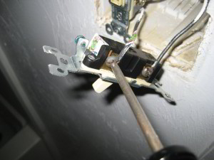 photograph or write down the arrangement. If the black wires are attached to the terminals on the sides of the switch, back the screws out and remove the wires. One black wire should be attached to the brass screw; this is the hot wire. The other black wire attached to the silver screw travels to the fixture. If the wires are pushed in the holes on the back, there is a small hole above each wire. Push a small nail into the hole and pull the wire out. The copper ground is usually attached to a green screws on the bottom of the switch. Back this screw out and detach the ground. Reattach the wires to the proper terminals on the new switch.
Once connected, push the new switch back into the box. Do not allow any of the wires to have a sharp kink. They will usually accordion back in and fold nicely unless the box is to full. Align the switch attachment screws at the top and bottom of the box and screw the switch into the box. The tabs at the top and bottom of the outlet should rest against the drywall. If the switch goes back too far, you will need to insert spacers behind the attachment screws and the box in the wall. Reinstall the cover plate.
Three-way and four-way switches – Replacing these switches can be confusing when you look at all the wires. Take a photo of the wires and to what terminals they are attached to. Replacing the switch is easy if you follow the instructions in the single pole switch. Just be sure to get the wires back on the SAME terminals.
If you are unsure of your skills or ability, contact a qualified technician to perform the work.